Filter Installation Guide
The following are guidelines for installation of Instec Filters. Failure to follow these guidelines may result in damage to the filter or the device into which it is being installed.
Solder-In Filters
Instec solder-in filters are multilayer ceramic discoidal capacitors assembled inside of a metal can. Care needs to be taken during installation of these devices not to thermally shock the capacitors. Solder-in filters MAY NOT be plunged directly into a solder pot. If pre-tinning is done to the filter body, DO NOT place the filter directly into cleaning solvent after soldering. Allow for cooling to below 80°C prior to submersing the filters in cleaning solvent.
As is the case with soldering ceramic capacitors, controlling temperature excursions of solder in filters is key. Preheating the component to within 50°C is ideal, when possible. In any case, controlling the rate of heating and cooling to a maximum of 3°C per second is highly recommended. Many times the cooling rate is ignored or forced by fans. Failure to control cooling is just as important as controlling the heating cycle. Low melting point solders, such as 60/40 (Sn/Pb), should be selected for attaching the body of the filter to the chassis as well as for soldering the terminals.
When attaching the filter bodies to the chassis using a soldering iron, use a controlled soldering iron (15-20 watts or less) with a maximum tip temperature of 275°C. Limit the dwell time on the body to 5 seconds maximum.
When attaching wires to the terminals, use of a head-sink is preferred. The heat-sink should be placed close to the body of the filter to limit the heat flow to the capacitor inside. When using a solder iron to solder to the terminals, use a controlled soldering iron (15-20 watts or less) with a maximum tip temperature of 275°C. Limit the dwell time on the lead to 5 seconds maximum.
Bolt-style filters
Instec Bolt-Style Filters are supplied with hardware including internal tooth star washers and panel nuts. Careful installation of the filter and hardware will prevent damage to the capacitor and other elements of the filter. Maximum recommended mounting torque (see table below) should be applied to the nut only. Exceeding maximum torque may result in damage to the filter. Flexing or bending terminals near the body of the filter should be avoided. When bending of leads is required, the lead close to the body should be clamped so that the stress of the bend isn’t transferred to the internal components of the filter. If other than straight leads are required in the application, consider buying Instec hooked leads such as those in the photo herein. Instec process fixturing provides stress relief to the internal compoennts when the hooks are formed.
Filter plates
Consider outsourcing your filter plate assembly to Instec. We can assist with your plate design (if desired), do the assembly work, perform 100% electrical screening and inspection, and take any yield loss. The resulting filter plates will meet your drawings with 100% yield.
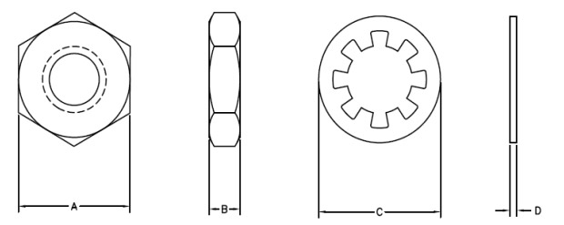
Typical Nut and Washer Dimensions
| Nut & Washer | A Dim In (mm) | B Dim In (mm) | C Dim In (mm) | D Dim In (mm) | Recommended Torque in-lbs (Nm) |
|---|---|---|---|---|---|
| 4-40 UNC-2A | 0.180/0.187 (4.57/4.75) | 0.057/0.067 (1.45/1.70) | 0.215/0.225 (5.46/5.72) | 0.010/0.020 (0.25/0.51) | 1.5 (0.17) |
| 8-32 UNC-2A | 0.241/0.250 (6.12/6.35) | 0.063/0.073 (1.60/1.85) | 00.275/0.285 (6.99/7.24) | 0.015/0.025 (0.38/0.64) | 4 (0.452) |
| 12-32 UNCF-2A | 0.241/0.250 (6.12/6.35) | 0.063/0.073 (1.60/1.85) | 0.372/0.383 (9.45/9.73) | 0.013/0.025 (0.33/0.58) | 6 (0.678) |
| 1/4-28 UNF-24 | 0.308/0.311 (7.82/7.90) | 0.091/0.096 (2.31/2.44) | 0.396/0.408 (10.06/10.36) | 0.015/0.021 (0.38/0.53) | 7 (0.791) |
| 5/16-24 UNF 24 | 0.365/0.377 (9.27/9.58) | 0.091/0.096 (2.31/2.44) | 0.425/0.435 (10.80/11.05) | 0.017/0.027 (0.43/0.69) | 7 (0.791) |
Please reference our Case Dimensions guidelines to help narrow down your sizing options.